
Magnetic Levitation
This project was built as a part of my Physics 2 class (Electricity and Magnetism). The photo gallery outlines the build process of an Arduino controlled magnetic levitation system. This setup uses an electromagnet to levitate a permanent magnet, or any object with a magnet inside it. I employed a hall effect sensor for position sensing, a MOSFET for switching the electromagnet on and off, and an Arduino to control these components in a closed loop feedback system.

The first step was to wind the electromagnet. I used a 1/2" low carbon steel rod as the core of the magnet.

I set this up in the lathe with acrylic rings as stops. I used 18 AWG enameled copper wire.
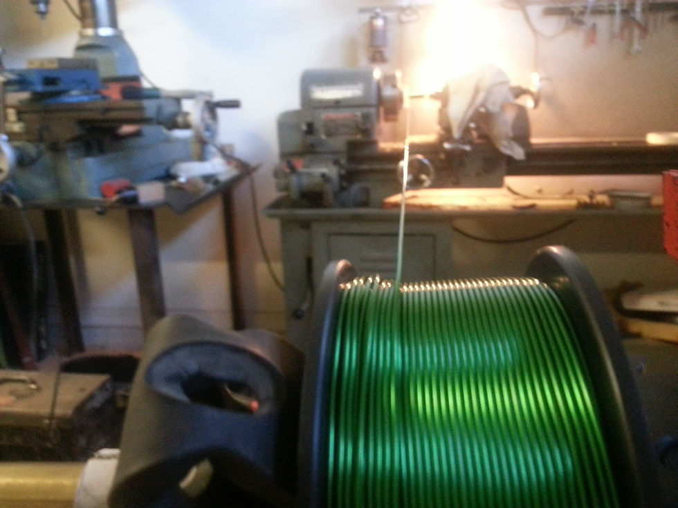
Wire spool set up a distance from the lathe. I kept tension on the wire to keep a tight coil while the lathe was running at about 50-75 RPM.
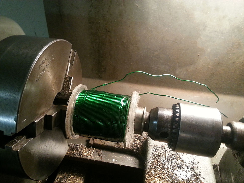
Once I was finished winding, I coated the coil in epoxy to keep it from unwinding. The final dimensions are about: 2" diameter by 2" length, 2 ohms of resance and roughly 8 miliHenrys of inductance

I used 1/4 acrylic sheet as the enclosure material. The pieces were cut on the table saw.
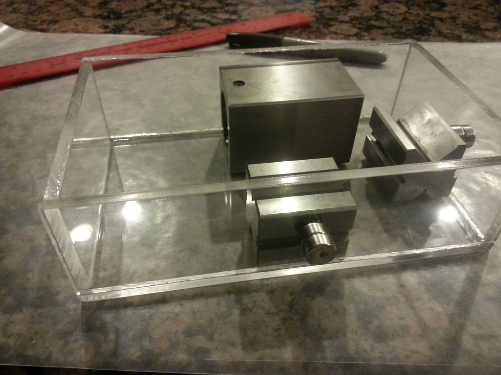
I used some square blocks of steel during gluing to keep the sides square.

I used some steel wire to mount the prototype board on top of the Arduino.


Verifying the component spacing. The wireless power transformer is on the right, the Arduino, circuit board on the left.


The wireless power antenna is a square of copper sheet which is positioned under the levitating lightbulb.

I used 3/4 copper pipe to create the electromagnet mount. The piece on the right is a 3/4 to 1" copper tee that has been slit and bent apart.